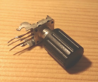
Here is a picture of a rotary encoder. I extended the contacts with pieces of wire to mount the encoder on a bread board:
Rotary encoders typically have 3 connectors, one goes to GND, the other two A and B carry the information if the knob was turned and to what direction (left/right). The following picture tries to illustrate what happens:

Rotary encoders are mechanical switches, and all mechanical switches have the problem that the signal looks not always as nice as I've drawn it it in the picture. I've done a measurement with my oscilloscope to visualize this. Here is the setup:


The center pin is connected to GND while the A and B connectors are tied to VCC with pull-up resistors. On the right picture the scope probes are visible. They tab the signal at A and B.
Turning the knob gives the following picture on the scope:


The first picture shows the overall signal and looks similar to the ideal one, except that the edges are not very clean. Zooming into one of the edges shows the trace bouncing around before getting to GND level. That has to be taken into account when writing the software for the decoding of the signal.
Hardware
To visualize the effect or turning the knob I've use 4 LEDs. The program has an internal counter that counts from 0 to 3. Turning the knob left counts up, turning it right counts down. The LED indicate at which position the counter is. The final hardware setup to test the rotary encoder can be seen in the following picture. The connections to the programmer are exactly as in my earlyer "Getting Started" post.

And here you can see it in motion:
Firmware
Naively, one could just try to check for a transition of A from high to low while B is low to detect a left turn, and a transition of B from high to low while A is low for the other direction. This doesn't work reliably because of the bouncing of signals.
Instead, the firmware is implemented as a state machine with states corresponding to the ones indicated in the schematic drawing in the beginning of this post. The state machine starts in state 0 and a transition to 1 can only be induced by B going from high to low. If A goes from high to low in state 0, the state machine would go to state 4 (going backwards). Being in state 1, a transition of B from low to high would go back to state 0, whereas a transition of A from high to low would lead to state 2. The knob was turned by one step if the state makes a full cycle from 0 to 0. The machine is implemented as a big switch() statement. Here is the code:
int8_t rotEnc(uint8_t *state, uint8_t pin, uint8_t bitA, uint8_t bitB)
{
 uint8_t A = pin & (1<<bitA);
 uint8_t B = pin & (1<<bitB);

 switch(*state)
 {
  case 0:
   if (!B) {
    *state = 3;
    return -1;
   }
   if (!A) {
    *state = 1;
    return 0;
   }
  case 1:
   if (A) {
    *state = 0;
    return 0;
   }
   if (!B) {
    *state = 2;
    return 0;
   }
  case 2:
   if (B) {
    *state = 1;
    return 0;
   }
   if (A) {
    *state = 3;
    return 0;
   }
  case 3:
   if (!A) {
    *state = 2;
    return 0;
   }
   if (B) {
    *state = 0;
    return  1;
   }
 }
 return 0;
}
The function takes a pointer to the state, a PIN register and two numbers indicating at which pins the A and B encoder outputs are connected. In my case (A=PC2, B=PC0) , the pin argument is PINC, bitA = 2 and bitB = 0.
The function returns 1 or -1 if a full cycle through the states is completed, 0 otherwise.
The main function is simple. The variable cnt is increased/decreased whenever the rotEnc function detects the completion of a full cycle through the all states. The state has to be stored in the main function. That makes the rotEnc function reusable if there are multiple rotary encoders connected to the microcontroller.
int main(void)
{
 // enable the LED ouputs
 DDRD = (1 << PD0) | (1 << PD1) | (1 << PD2) | (1 << PD3);

 DDRC = 0; // port C as input
 PORTC = (1 << PC0) | (1 << PC2); // enable pull-ups for PC0 (A) and PC2 (B)

 int16_t cnt = 0;
 uint8_t state = 0;

 while(1)
 {
  cnt += rotEnc(&state,PINC,2,0);

  if (cnt > 3) cnt = 0;
  if (cnt < 0) cnt = 3;

  PORTD = (1 << cnt);
 }

 return 0 ;
}
That was an example that used digital I/O for the task of user interaction.
Keine Kommentare:
Kommentar veröffentlichen